FRIZLEN
Description
Englische standard Test Beschreibung. Diese Beschreibung wird immer dann ausgegeben, wenn keine Beschreibung auf der jeweiligen Seite vorhanden ist.

Safety instructions for application and installation of power resistors
Please check also the „Dimension Sheet“ and „Technical List“ of the respective device.
Intended applications
A power resistor is a passive component that must be used according to its sizing and taking into account the safety instructions for application and installation.
A power resistor has been designed for one or several of the following applications:
- Braking, chopper or starting resistor for electric drive applications
- Load and testing resistor
- Damping resistor
- Snubber circuit resistor
- Earthing resistor
- Heating resistor for cabinets
- Limiting series resistor
Any application differing from the aforementioned is not permitted.
The power resistor must not be remodeled or modified.
Safety indications
Operational safety can only be assured if the resistor is installed and maintained by qualified and electrically instructed persons.
For installation and maintenance of resistors the personal protective equipment (PPE) must be worn.
Using an inappropriate resistor can cause damage to property or injury to persons.
The resistor must not be overloaded beyond its specifications and should be protected against overloading by appropriate measures.
The resistor can become very hot under load and must be protected against unwanted contact.
There must be enough space around the resistor. A sufficient supply of cooling air and transportation of hot air away from the resistor must be assured.Within close proximity to the resistor neither flammable parts nor explosive zones are allowed.
How to reduce remaining hazards
FRIZLEN offers several factory-provided options to protect a resistor against thermal overloading.
This includes (depending on the favoured type series):
- Installation of bi-metal temperature switch
Installation of a thermal overload relay
You will find more information about safe resistors checking out www.frizlen.com/en/safe-resistors.
Technical data of the resistor
Refer to the technical list of the type series or type data sheet and the type plate of the resistor.
Maximum ambient temperature: 40°C.
For higher ambient temperatures the continuous dissipation must be derated by 4% per 10 K temperature rise!
Allowed humidity range (at operation): 5% up to 85% (not condensating).
Installation of the resistor
The allowable installation positions can be taken from the dimension sheet of the respective type series.
The resistor must be installed on a heat resistant surface. If installed vertically the connection terminals and cables must be located on the bottom side of the resistor.
Any installation must be done according to the designated protection degree.
For installations of resistor devices with open bottom sides any outstanding elements on the mounting surface that could underrun the necessary air and creepage distance must be removed.
Recommended minimum distances to surrounding parts, walls and ceiling can be taken from the table below:.
| Continuous power rating of the resistor |
Installation
|
Side distance and between resistors
|
Distance below the resistor
|
Distance above the resistor
|
Up to 1 kW
|
Horizontally
|
200 mm
|
Not applicable
|
350 mm
|
Vertically (wall)
|
150 mm
|
250 mm
|
300 mm
| |
Up to 10 kW
|
Horizontally
|
300 mm
|
Not applicable
|
650 mm
|
Vertically (wall)
|
250 mm
|
350 mm
|
600 mm
| |
Up to 22 kW
|
Horizontally
|
400 mm
|
Not applicable
|
750 mm
|
Vertically (wall)
|
350 mm
|
400 mm
|
700 mm
| |
Up to 44 kW
|
Horizontally
|
500 mm
|
Not applicable
|
850 mm
|
Vertically (wall)
|
Not applicable
|
Not applicable
|
Not applicable
| |
Up to 88 kW
|
Horizontally
|
600 mm
|
Not applicable
|
1000 mm
|
Vertically (wall)
|
Not applicable
|
Not applicable
|
Not applicable |
Horizontal installation: e.g. on the floor, on top of a cabinet, on a table or similar
Vertical installation: e.g. on the wall, on a mounting plate for cabinets or similar
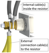
Connection to bolt type terminals

Valid for: bolt type terminals without current conduction
(External Connection cables and cables inside the resistor are both mounted on the same side of the bolt.)
The cable shoes of the external cables must be mounted in the way as shown in the picture.
| Recommended tightening torque (according to the norm DIN 46200) | |
|---|---|
| M6 | 3 Nm |
| M8 | 6 Nm |
| M10 | 10 Nm |
| M12 | 15,5 Nm |
Hazard note for devices with protection degree IP00
| Resistors with protection degree IP00 must be equipped with an appropriate protection housing or must be installed into a protected device or cabinet. Otherwise there is a hazard of electric shock and thermal burning. For installations of IP00 resistors into any housing the necessary air and creepage distances between conducting resistor parts and ambient parts must be complied with. |
Initial operation
Before any initial operation it must be assured
- the intended protection degree is complied with
- all connection cables are installed properly
- the waste heat can be dissipated properly
- all installation notes on the dimension sheet have been observed
- the insulation resistance of the resistor is at least 1 MOhm (measured between housing and resistor)
Any question concerning power resistor and safety issues?

Please contact me so I can help you!
Simon Zimmermann
Technical Sales
+49 (0)7144 8100 - 49
info(at)frizlen.com
I´m looking forward to getting in contact with you!
Kontakt
FRIZLEN GmbH u. Co KG.
Gottlieb-Daimler-Straße 61
D-71711 Murr
![]() E-Mail
E-Mail![]() +49 (0) 71 44 81 00-0
+49 (0) 71 44 81 00-0![]() +49 (0) 71 44 20 76 30
+49 (0) 71 44 20 76 30